GRE Tunnel Configuration
Generic Routing Encapsulation, or GRE, is a tunneling protocol that allows the encapsulation of many different network layer protocols between two endpoints. Packets are sent through a virtual tunnel on a point-to-point link.
It is important to understand that GRE tunnels do not encrypt traffic in any way; they are simply encapsulated within an additional GRE and IP header. If a secure tunnel is required, IPSec can be used with GRE to provide data confidentiality.
Also keep in mind that GRE over IPSec tunnels are different from stand-alone IPSec VPN tunnels. GRE over IPSec tunnels support multicast IP traffic, which strict IPSec VPNs do not. This is important when routing protocols need to send routing information across the tunnel since they use multicast for their control information. If your network requires a routing protocol like EIGRP or OSPF, then GRE over IPSec can provide secure transport for those services.
Step 1: Create the tunnel interface on the VPN router.
A GRE tunnel uses a virtual tunnel interface, configured with an IP address where packets are encapsulated/decapsulated as they enter and exit the GRE tunnel.
The IP address must be in the same subnet on both router’s tunnel interfaces.
interface Tunnel0
ip address 172.16.1.1 255.255.255.0
It is common practice to also reduce the maximum transmission unit (MTU) to 1400 bytes to avoid any fragmentation problems over the transport networks. Remember that GRE adds an additional 20-byte IP header as well as a 4-byte GRE header to each packet in the tunnel.
Because most devices have an MTU of 1500 bytes, reducing the GRE tunnel MTU will account for the added overhead and help prevent unnecessary packet fragmentation.
interface Tunnel0
ip address 172.16.1.1 255.255.255.0
ip mtu 1400
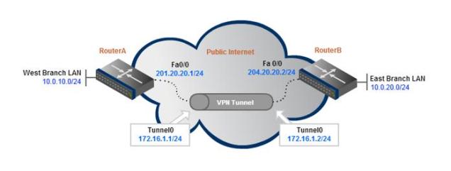
Step 2: Define the tunnel source and destination under each tunnel interface.
The router uses its local interface that connects to the internet as its tunnel source. The tunnel destination corresponds to the remote router’s publicly routable IP address.
interface Tunnel0
ip address 172.16.1.1 255.255.255.0
ip mtu 1400
tunnel source FastEthernet0/0
tunnel destination 204.20.20.2
Note that the tunnel source and destination can both be IP addresses. For example, “tunnel source 201.20.20.1″ could have been used instead of “tunnel source FastEthernet0/0″.
Step 3: Testing Connectivity
The configuration above is from the perspective of RouterA. The same configuration template would need to be applied to RouterB for the tunnel to begin passing traffic (with source/destination IPs swapped of course).
Now that both endpoint routers have been configured, they should be reachable via pings.
ping 172.16.1.2
Type escape sequence to abort.
Sending 5, 100-byte ICMP Echos to 172.16.1.2, timeout is 2 seconds:
!!!!!
Success rate is 100 percent (5/5), round-trip min/avg/max = 1/2/4 ms
Step 4: Add Routes to Remote Networks
This confirms that we can pass traffic inside the GRE tunnel, but hosts on the Branch LAN networks will not be able to send packets to each other without some routes added. We can use a simple static route for this purpose.
RouterA(config)# ip route 10.0.20.0 255.255.255.0 172.16.1.2
RouterB(config)# ip route 10.0.10.0 255.255.255.0 172.16.1.1
Now when RouterA receives a packet destined for the East Branch LAN (10.0.20.0/24), it knows it’s next-hop interface is the tunnel endpoint, so it will forward the packet through the GRE tunnel.
That’s it for the GRE tunnel configuration. Now onto adding IPSec.
IPSec Encryption for the GRE Tunnel
As we mentioned, GRE provides no form of payload confidentiality or encryption. If the packet are sniffed over the public transit networks, their contents are in plain-text.
IPSec solves the security concerns by encrypting part or all of the GRE packets. There are two IPSec tunnel modes – tunnel and transport. This configuration example will show the default, tunnel-mode IPSec encryption which protects they entire GRE header and payload.
Step 1: Create an Access list to define the traffic to encrypt.
The ACL should match traffic from the outside interface of the local router to the outside interface of the remote router.
access-list 101 permit gre host 201.20.20.1 host 204.20.20.2
Step 2: Configure an isakmp policy.
Note: The ISAKMP policy, key, and IPSec transform set must match on both sides of a single tunnel.
crypto isakmp policy 1
authentication pre-share
Step 3: Configure pre-shared keys.
The key P@ssword will be configured to be used for authentication with RouterA’s peer 204.20.20.2. The address at the end of the statement refers to the public IP address of the peer router (RouterB).
crypto isakmp key P@ssword address 204.20.20.2
Step 4: Configure the transform set.
crypto ipsec transform-set strong esp-3des esp-md5-hmac
The full ISAKMP configuration:
crypto isakmp policy 1
authentication pre-share
crypto isakmp key P@ssword address 204.20.20.2
!
crypto ipsec transform-set strong esp-3des esp-md5-hmac
Step 5: Configure a crypto map and bind the transform set and the traffic ACL to the crypto map. Define peer IP address below crypto map.
crypto map S2SVPN 10 ipsec-isakmp
set peer 204.20.20.2
set transform-set strong
match address 101
Step 6: Apply the crypto map to the physical, outside interface.
If you are running a version of IOS Software Release earlier than 12.2.15 then the crypto map must be applied to the tunnel interface as well as the physical interface.
interface FastEthernet0/0
crypto map S2SVPN
interface Tunnel0
crypto map S2SVPN
Now configure the remote router using the same IPSec configuration template. Make sure to change the local and remote IPs as necessary.
Verify GRE over IPSec Tunnel Connectivity
Now that the GRE over IPSec tunnel configuration is complete, we can verify end-to-end IPSec tunnel connectivity. By simply sending pings to the remote networks, the IPSec VPN will come up and begin encrypting/decrypting traffic.
RouterA# ping 10.0.10.1
Type escape sequence to abort.
Sending 5, 100-byte ICMP Echos to 10.0.10.1, timeout is 2 seconds:
!!!!!
Success rate is 100 percent (5/5), round-trip min/avg/max = 1/3/4 ms
The show crypto session command can be used to verify that the IPSec VPN encryption is operational.
RouterA# show crypto session
Crypto session current status
Interface: Tunnel0
Session status: UP-ACTIVE
Peer: 200.20.20.2 port 500
IKE SA: local 201.20.20.1/500 remote 204.20.20.2/500 Active
IPSEC FLOW: permit 47 host 201.20.20.1 host 204.20.20.2
Active SAs: 2, origin: crypto map


