MystaJoneS

If you're not making mistakes, then you're not doing anything.

  • Verify Cisco AVC licensing is active

    router#show license

    Verify current NBAR information

    router# show ip nbar protocol-pack active

    Verify the version of NBAR

    router#sh ip nbar version | include software

    Installing a new protocol pack

    router#ip nbar protocol-pack flash0:/pp-adv-isrg2-152-4.M1-13-5.1.0.pack

    View NBAR traffic on an interface

    router#sh ip nbar protocol-discovery [interface]

    That’s about it.


    + ,
  • GRE Tunnel Configuration

    Generic Routing Encapsulation, or GRE, is a tunneling protocol that allows the encapsulation of many different network layer protocols between two endpoints. Packets are sent through a virtual tunnel on a point-to-point link.

    It is important to understand that GRE tunnels do not encrypt traffic in any way; they are simply encapsulated within an additional GRE and IP header. If a secure tunnel is required, IPSec can be used with GRE to provide data confidentiality.

    Also keep in mind that GRE over IPSec tunnels are different from stand-alone IPSec VPN tunnels. GRE over IPSec tunnels support multicast IP traffic, which strict IPSec VPNs do not. This is important when routing protocols need to send routing information across the tunnel since they use multicast for their control information. If your network requires a routing protocol like EIGRP or OSPF, then GRE over IPSec can provide secure transport for those services.
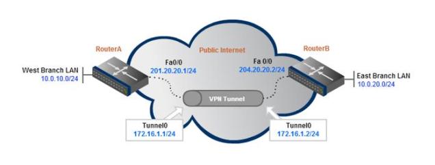
    GRE-Tunnel Config - Basic

    Step 1: Create the tunnel interface on the VPN router.

    A GRE tunnel uses a virtual tunnel interface, configured with an IP address where packets are encapsulated/decapsulated as they enter and exit the GRE tunnel.

    The IP address must be in the same subnet on both router’s tunnel interfaces.

    interface  Tunnel0

    ip address 172.16.1.1 255.255.255.0

    It is common practice to also reduce the maximum transmission unit (MTU) to 1400 bytes to avoid any fragmentation problems over the transport networks. Remember that GRE adds an additional 20-byte IP header as well as a 4-byte GRE header to each packet in the tunnel.

    Because most devices have an MTU of 1500 bytes, reducing the GRE tunnel MTU will account for the added overhead and help prevent unnecessary packet fragmentation.

    interface  Tunnel0

    ip address 172.16.1.1 255.255.255.0

    ip mtu 1400

    Step 2: Define the tunnel source and destination under each tunnel interface.

    The router uses its local interface that connects to the internet as its tunnel source. The tunnel destination corresponds to the remote router’s publicly routable IP address.

    interface  Tunnel0

    ip address 172.16.1.1 255.255.255.0

    ip mtu 1400

    tunnel source FastEthernet0/0

    tunnel destination 204.20.20.2

    Note that the tunnel source and destination can both be IP addresses. For example, “tunnel source 201.20.20.1″ could have been used instead of “tunnel source FastEthernet0/0″.

    Step 3: Testing Connectivity

    The configuration above is from the perspective of RouterA. The same configuration template would need to be applied to RouterB for the tunnel to begin passing traffic (with source/destination IPs swapped of course).

    Now that both endpoint routers have been configured, they should be reachable via pings.

    ping 172.16.1.2

    Type escape sequence to abort.

    Sending 5, 100-byte ICMP Echos to 172.16.1.2, timeout is 2 seconds:

    !!!!!

    Success rate is 100 percent (5/5), round-trip min/avg/max = 1/2/4 ms

    Step 4: Add Routes to Remote Networks

    This confirms that we can pass traffic inside the GRE tunnel, but hosts on the Branch LAN networks will not be able to send packets to each other without some routes added. We can use a simple static route for this purpose.

    RouterA(config)# ip route 10.0.20.0 255.255.255.0 172.16.1.2

    RouterB(config)# ip route 10.0.10.0 255.255.255.0 172.16.1.1

    Now when RouterA receives a packet destined for the East Branch LAN (10.0.20.0/24), it knows it’s next-hop interface is the tunnel endpoint, so it will forward the packet through the GRE tunnel.

    That’s it for the GRE tunnel configuration. Now onto adding IPSec.

    IPSec Encryption for the GRE Tunnel

    As we mentioned, GRE provides no form of payload confidentiality or encryption. If the packet are sniffed over the public transit networks, their contents are in plain-text.

    IPSec solves the security concerns by encrypting part or all of the GRE packets. There are two IPSec tunnel modes – tunnel and transport. This configuration example will show the default, tunnel-mode IPSec encryption which protects they entire GRE header and payload.

    Step 1: Create an Access list to define the traffic to encrypt.

    The ACL should match traffic from the outside interface of the local router to the outside interface of the remote router.

    access-list 101 permit gre host 201.20.20.1 host 204.20.20.2

    Step 2: Configure an isakmp policy.

    Note: The ISAKMP policy, key, and IPSec transform set must match on both sides of a single tunnel.

    crypto isakmp policy 1

      authentication pre-share

    Step 3: Configure pre-shared keys.

    The key P@ssword will be configured to be used for authentication with RouterA’s peer 204.20.20.2. The address at the end of the statement refers to the public IP address of the peer router (RouterB).

    crypto isakmp key P@ssword address 204.20.20.2

    Step 4: Configure the transform set.

    crypto ipsec transform-set strong esp-3des esp-md5-hmac

    The full ISAKMP configuration:

    crypto isakmp policy 1

      authentication pre-share

    crypto isakmp key P@ssword address 204.20.20.2

    !

    crypto ipsec transform-set strong esp-3des esp-md5-hmac

    Step 5: Configure a crypto map and bind the transform set and the traffic ACL to the crypto map. Define peer IP address below crypto map.

    crypto map S2SVPN 10 ipsec-isakmp

    set peer 204.20.20.2

    set transform-set strong

    match address 101

    Step 6: Apply the crypto map to the physical, outside interface.

    If you are running a version of IOS Software Release earlier than 12.2.15 then the crypto map must be applied to the tunnel interface as well as the physical interface.

    interface FastEthernet0/0

      crypto map S2SVPN

    interface Tunnel0

      crypto map S2SVPN

    Now configure the remote router using the same IPSec configuration template. Make sure to change the local and remote IPs as necessary.

    Verify GRE over IPSec Tunnel Connectivity

    Now that the GRE over IPSec tunnel configuration is complete, we can verify end-to-end IPSec tunnel connectivity. By simply sending pings to the remote networks, the IPSec VPN will come up and begin encrypting/decrypting traffic.

    RouterA# ping 10.0.10.1

    Type escape sequence to abort.

    Sending 5, 100-byte ICMP Echos to 10.0.10.1, timeout is 2 seconds:

    !!!!!

    Success rate is 100 percent (5/5), round-trip min/avg/max = 1/3/4 ms

    The show crypto session command can be used to verify that the IPSec VPN encryption is operational.

    RouterA# show crypto session

    Crypto session current status

    Interface: Tunnel0

    Session status: UP-ACTIVE

    Peer: 200.20.20.2 port 500

    IKE SA: local 201.20.20.1/500 remote 204.20.20.2/500 Active

    IPSEC FLOW: permit 47 host 201.20.20.1 host 204.20.20.2

    Active SAs: 2, origin: crypto map

    + , ,
  • What is Iceweasel?

    Iceweasel is a fork [from Firefox] with the following purpose :

    1. backporting of security fixes to declared Debian stable version.

    2. no inclusion of trademarked Mozilla artwork (because of #1 above)

    Beyond that, they will be basically identical.

    Step # 01
    Launch the browser and download the Flash Player in a separate folder.
    Download link = http://get.adobe.com/flashplayer/
    (Note: Version to download tar.gz for other Linux)

    Step # 02
    Launch the terminal and open the folder path where downloaded flash file is stored then run the following command.

    Code: tar xzvf install_flash_player_11_linux.i386.tar.gz

    or

    Code: tar xzvf install_flash_player_11_linux.x86_64.tar.gz

    If in case your downloaded file having some another name then put that file name during extracting

    Code: tar xzvf yourdownloadedfilename.tar.gz

    Step # 3
    Now run the following last command (Remember: Do not change the folder path stay in the same folder where you unpacked the files)

    Code: cp libflashplayer.so /usr/lib/mozilla/plugins/
    + ,
  • In the first CLI session, run tcpdump on the LAN interface. In the second CLI session, run tcpdump on the WAN interface and in the third CLI session, ping the IP address fo the host which traffic doesn’t get optimised

    Open up three sessions

    Three CLI sessions via SSH to the RB for troubleshooting:

    riverbed-sh#tcpdump -ni lan0_0 icmp

    riverbed-sh#tcpdump -ni wan0_0 icmp

    riverbed-sh#ping -I ip to ip

    Troubleshooting Riverbed®Steelhead® WAN Optimizers

    + ,
  • A quick guide to setting up a GSM on a ISR using EHWIC-3G-HSPA+7.  You must get the data service account from you service provider, in turn you will receive a SIM card that you can install on to the EHWIC and an APN (Access Point Name) required to create a profile.

    Insert the SIM card into the EHWIC, insert in the router and power up the device.

    Chat scripts are strings fo text used to send commands for modems dialing to log in to remote systems, and to initialise asynchronous devices connected to an asynchronous line. 3G Wan interface should be treated just like any other async interface and the following chat script show the required information to connect to the GSM network, using a carrier-specific dial string and timeout value of 30 seconds.

    Step 1: Create a chat script

    chat-script [script-name] [script]

    Example

    chat-script GSM “” “AT!SCACT=1,1” TIMEOUT 30 “OK”

    Step 2: Apply the chat script to the asynchronous line

    line [Cellular-Interface-Number]

    script dialer [Script-Name]

    Example

    line 0/1/0

    script dialer GSM

    Next, we create a GSM profile.

    Step 3: From enable mode, use the profile to identify the username and password provided to you by your service provider. Use the cellular interface identifier and keyword GSM.

    cellular [Cellular-Interface] gsm profile create [Sequence-Number] [AP-Name]

    Tech Tip – This step should be created from enable mode and not conf mode.

    Example

    cellular 0/1/0 gsm profile create 1 telstra.corp

    + ,
  • A really useful command for unlocking the SIM while in the router.

    router#sh cell 0/1/0 security
    Card Holder Verification (CHV1) = Enabled
    SIM Status = Locked
    SIM User Operation Required = Enter CHV1
    Number of Retries remaining = 3

    router#cellular 0/1/0 gsm sim unlock NNNN
    !!!WARNING: SIM will be unlocked with pin=NNNN(4), call will be disconnected!!!
    Are you sure you want to proceed?[confirm]

    + ,
  • Switched Port Analyzer (SPAN) allows traffic to be replicated to a port from a specified source.  The traffic to be replicated can be from physical ports, virtual ports, or VLANs, but you cannot mix source types within a single SPAN session.  The most common reason for SPAN to be employed is for packet capture.  If you need to capture the traffic on VLAN 10, for example, you can’t just plug a sniffer on a port in that VLAN, as the switch will only forward packets destined for the sniffer.  However, enabling SPAN with the VLAN as the source, and the sniffer’s port as the destination, will cause all traffic on the VLAN to be sent to the sniffer. SPAN is also commonly deployed when Intrusion Detection Systems (IDSs) are added to a network.  IDS devices need to read all packets in one or more VLANs, and SPAN can get the packets to the IDS devices.

    Using Remote Switched Port Analyzer (RSPAN), you can even send packets to another switch. RSPAN can be useful in data centers where a packet-capture device is permanently installed on one of many interconnected switches. With RSPAN, you can capture packets on switches other than the one with the sniffer attached (RSPAN configuration details are provided later in this section).

    Configure SPAN with the monitor command.

    switch(config)#monitor session 1 ?

    destination  SPAN destination interface or VLAN
    filter             SPAN filter
    source          SPAN source interface, VLAN

    Having more than one SPAN session is useful when you have an IDS device on your network and you need to do a packet capture. The IDS device will require one SPAN session, while the packet capture will use another.

    For a monitor session to be active, you must configure a source port or VLAN, and a destination port. Usually, I configure the destination port first because the packetcapture device is already attached. If you have port security set, you must disable it before you can use the port as a SPAN destination:

    switch(config)#monitor session 1 destination interface g1/0/20
    %Secure port can not be dst span port

    Sessions can be numbered from 1 to 66, but you can only have two sessions configured at any given time on a 3750 switch. Here, I have two sessions configured (session 1 and session 10):

     monitor session 1 source vlan 20 rx
     monitor session 1 destination interface Gi1/0/10
     !
     monitor session 10 source vlan 10 rx
     monitor session 10 destination interface Gi1/0/20

    If you try to configure more than two SPAN sessions on a 3750 switch, you will get the following error:

    switch(config)#monitor session 20 source int g1/0/10
    % Platform can support a maximum of 2 source sessions

    In this example, I’ve configured two VLANs to be the sources, both of which will have their packets reflected to interface Gi1/0/20:
     monitor session 10 source vlan 20 rx
     monitor session 10 source vlan 10
     monitor session 10 destination interface Gi1/0/20

    You can also monitor one or more interfaces. Multiple interfaces can be configured separately or on a single configuration line:

    switch(config)#monitor session 11 source interface g1/0/11
    switch(config)#monitor session 11 source interface g1/0/12

    Entering the two preceding commands adds the following line to the configuration:
     monitor session 11 source interface Gi1/0/11 – 12

    The sources in a monitor session can be configured as either receive (rx), transmit (tx), or both. The default is both:

    switch(config)#monitor session 1 source int g1/0/12 ?

     , Specify another range of interfaces
     – Specify a range of interfaces
    both Monitor received and transmitted traffic
     rx Monitor received traffic only
     tx Monitor transmitted traffic only
    <cr>
    Interfaces should usually be monitored in both directions, while VLANs should be monitored in only one direction.

    To see which SPAN sessions are configured or active, use the show monitor command:

    swtich#show monitor

    Displays the session info.

    To disable monitoring on a specific SPAN, you can delete the entire monitor session, remove all the sources, or remove the destination. All monitor commands can be negated:

    switch(config)#no monitor session 11 source interface Gi1/0/11 – 12

    You can remove all local SPAN, all RSPAN, or all SPAN sessions as a group by adding the local, remote, or all keywords:

    switch(config)#no monitor session ?
     <1-66>   SPAN session number
     all            Remove all SPAN sessions in the box
     local        Remove Local SPAN sessions in the box
     remote    Remove Remote SPAN sessions in the box

    You should always remove your SPAN sessions when you no longer need them. SPAN takes up system resources, and there can be confusion if someone plugs a device into the SPAN destination port.
    RSPAN works the same way that SPAN does, with the exception that the destination interface is on another switch. The switches must be connected with an RSPAN VLAN. To create an RSPAN VLAN, configure a VLAN and add the remote-span command:

    switch-1(config)#vlan 777
    switch-1(config-vlan)# remote-span

    If you’re running VTP, you may not need to create the VLAN, but you will still need to configure it for RSPAN. In either case, the steps are the same. On the source switch, specify the destination as the RSPAN VLAN:

    switch-1(config)#monitor session 11 destination remote vlan 777

    You can enter a destination VLAN that has not been configured as an RSPAN VLAN, but, alas, it won’t work.
    Now, on the destination switch, configure the same VLAN as an RSPAN VLAN. Once you’ve done that, configure a monitor session to receive the RSPAN being sent from the source switch:

    switch-2(config)#vlan 777
    switch-2(config-vlan)#remote-span
    switch-2(config)#monitor session 11 source remote vlan 777

    There is no requirement for the monitor session numbers to be the same, but as I like to say, simple is good. If you have not configured the source switch to be the RSPAN source, you will get an error:

    switch-2(config)#monitor session 11 source remote vlan 777
    % Cannot add RSPAN VLAN as source for SPAN session 11 as it is not a RSPAN Destination session

    When using RSPAN, don’t use an existing trunk for your RSPAN VLAN. SPAN can create a large amount of traffic. When you’re monitoring VLANs composed of multiple gigabit interfaces, the SPAN traffic can easily overwhelm a single gigabit RSPAN link. Whenever possible, set up a dedicated RSPAN VLAN link between the switches.

    + ,
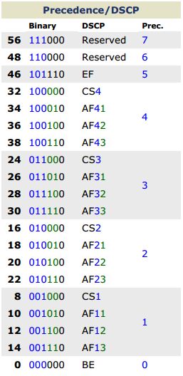
  • Prec-DSCP

    +
  • After many hours trying to sort this one out it would appear that a Riverbed Steelhead can’t easily optimise VC Traffic, as this traffic is already optimised by the Polycom device itself.  Sorry, that’s not to say I can’t, but i’d rather not enable the QoS on the Steelhead to solve this problem.

    The environment:

    H.323 protocol matched in the VC Class of traffic, in this case af41 (34). Packets tagged, no packets being dropped

    Running 6CoS on Telstra Links (GWIP) which is really just IPMAN.

    Host specific (/32) in-path optimisation rules on the Steelheads to ensure traffic to and from the VC units is bypassed.

    Under normal circumstances traffic is passed through the Steelhead and the the size of packet increases, as riverbed encapsulates video packets, so i have decided to bypass video traffic on the steelhead, so that the encapsulation and other overheads can be avoided.

    Fingers crossed….but i’m pretty happy it will work!

    + , , ,